Cooling Switches And Senders Explained-Michael Harding, July 2017 |
 When vehicles started coming off the showroom floor with fuel injection, we started to see more sensors and switches than ever before. It started to get more complicated, because electronic fuel injection requires a dedicated temperature sender for the computer, separate from the sender used for the gauge.
And then there was another sender that was used for the electric cooling fans, and these three temperature senders are typically not shared across components, as they are used for different purposes. Eventually, the fans could be triggered by the EFI computer, and the gauges could be fed by the computer, which stored all data thanks to onboard diagnostics (OBD).
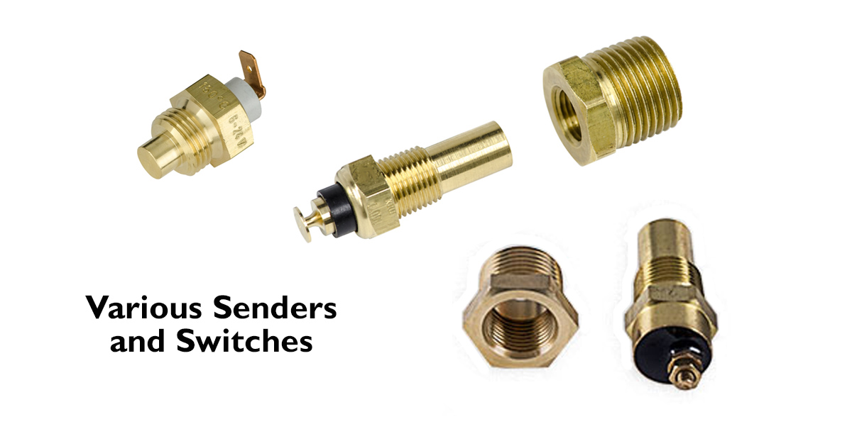
For classic cars, to operate a gauge the sender is a variable resistor that slowly allows more current to travel to the gauge as the engine gets warmer. If you take the wire off of this sender and ground it, you're essentially sending the full current to your gauge and it should peg at the highest temperature reading on the gauge itself.
The EFI computer uses a similar sender, which the computer interprets by the resistance in the sender. A cold engine will give a static temperature of about room temperature, and as the engine idles/runs, the resistance decreases and sends that info to the computer, much like it does for a temperature gauge.
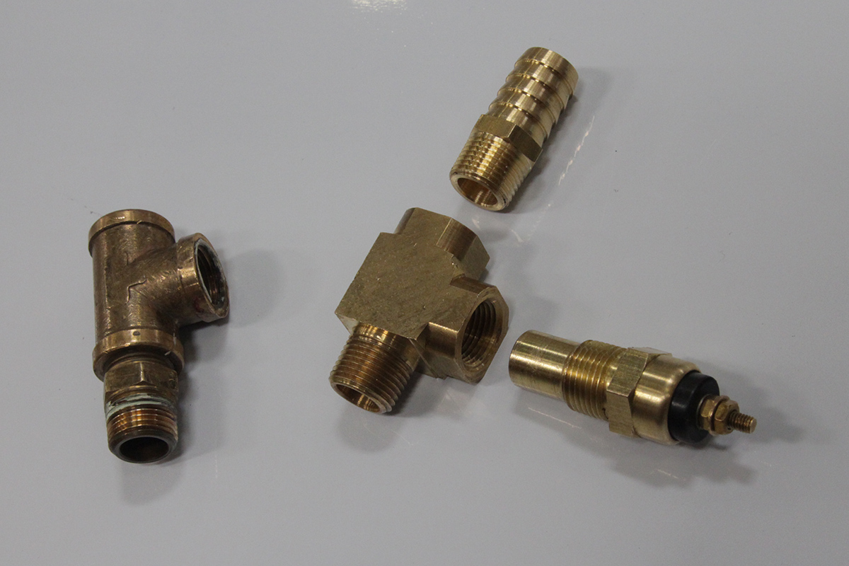
Since this is a two-wire sender direct from the manufacturer, the thread sealer is acceptable and won't interfere with sender operation. A single-wire sender must be installed without thread sealer or tape because it relies on the ground connection with the intake manifold.
A cooling fan, however, requires a different type of temperature sender, much like the one in our Fan Relay Kits. That sender contains a switch, rather than a variable resistor, and is either on or off. A cold engine will provide an open circuit, and no current can flow from the sender to the fan relay. Once the temperature rises to a set level, in this case about 185 degrees, the switch closes. This completes the ground circuit and if everything is wired correctly the fan relay clicks closed, and the fans come on. You would get the same result by grounding the wire from the relay directly; it completes the circuit.
Because the fan relay sender is just a switch, it doesn't detect variables in temperature like a typical gauge sender does. If you're coolant temperature is 125 degrees, it's the same as 0 to the sender, and it's switched off. If your coolant temperature is 210 degrees, it's the same as seeing 185 degrees, and it's switched on. This sender detects 185 degrees and turns on, and when the temperature drops to about 175 degrees, it turns off; about a 10 degree window is the difference between on and off.
For that reason, the relay sender cannot be shared or used for the temperature gauge inside the car. We had a customer call us and after months of everything working just fine, all of a sudden he had problems with his cooling system. After some conversation, we found out that the only thing that changed was that he added a temperature gauge under the dash. He wanted to keep the factory gauge, which only read C to H, but wanted an additional gauge that would tell him what the actual temperature is. However, he didn't have an extra port in the intake manifold for the new sender, so he used the fan relay sender and attached his new wire there. This caused a couple of problems, and some false readings.
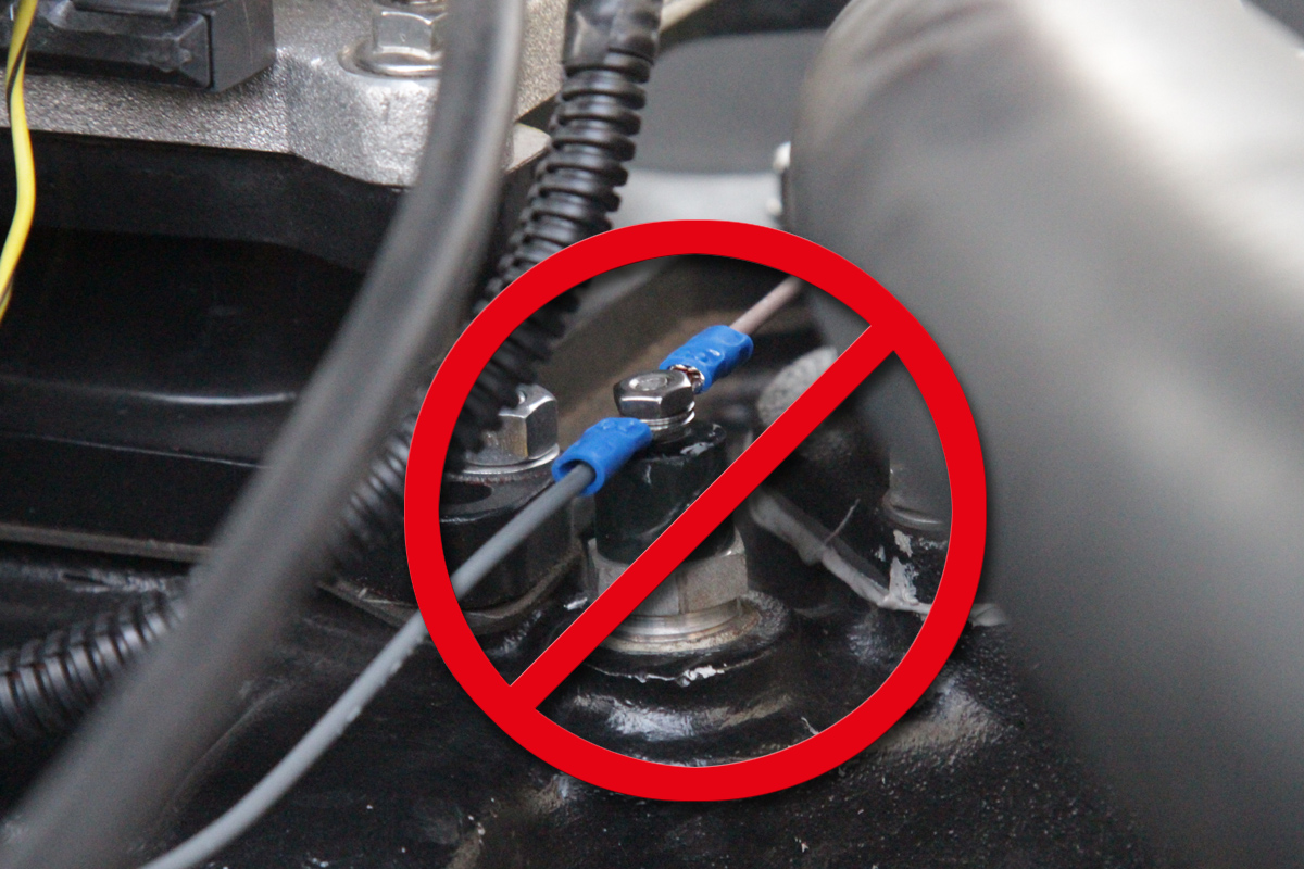
Our cooling fan sender is an on/off switch. By connecting the gauge wire, which requires a variable ohms sender, the signal is stolen from the relay. This results in the fans not turning on at all.
If he had kept driving around town, his temperature likely would have reached over 220, and his fans would probably never turn on because the gauge was stealing that signal. Shutting off where he did, he likely was only about 185 degrees - the point where the sender switches on - and not the higher temperature seen on the gauge. He also noted his factory gauge wasn't over in the "H" zone yet.
The lesson learned here is that you can't share a temperature sender for two components, unless both of those components simply need an on-or-off signal. Gauge manufacturers will include a sender with their gauge and recommend not using a sender from another company or gauge because of differences in readings. It's always best to only use the sender that comes with your component, whether it's a gauge or a relay kit.
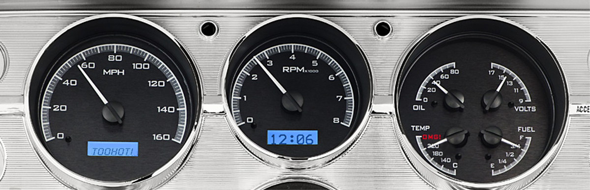
If you connect the gauge wire to a fan relay sender, you'll see no reading until the temperature reaches 185 degrees when the sender switches on, and then the gauge will peg, giving a false reading.
So what can you do if you don't have any extra ports for the new sender? We'll answer that one below, because there are some tricky options that will give you another port or two, and sometimes you just have to get a little creative. We'll show you two methods that are simple and affordable.
Running Out Of Ports For Senders
One common problem we see with older intake manifolds is that people tend to run out of ports when they're upgrading their vehicle with modern amenities, like fuel injection and electric cooling fans. Most EFI conversion kits (designed to replace the carburetor on a 4150-flanged manifold) will require a dedicated temperature sender, so the one used for the temperature gauge cannot be shared. Add an electric cooling fan, and there's another port needed for the switch to turn on the relays. One advantage to the EFI conversion kits is that there is a dedicated output to use for electric fan relays, and the EFI controller can be used to switch the fans on at a set temperature, and off again when the temperature drops below a certain point. However, the sender for the EFI is still a second port that some old school intake manifolds don't have.
You can get creative, but it's important to remember that you want the sender to access the coolant reading from below the thermostat, not above. That way you can get a proper temperature reading.
Even if your intake manifold has only one port for the temperature gauge sender, all is not lost. There are ways to get around this by using a thermostat spacer or a brass T-fitting. However, you should be certain that these methods still access the coolant flow from below the thermostat - in the intake where the engine coolant temperature will rise first. If your sender reads the temperature after the thermostat opens, then it might not function properly.
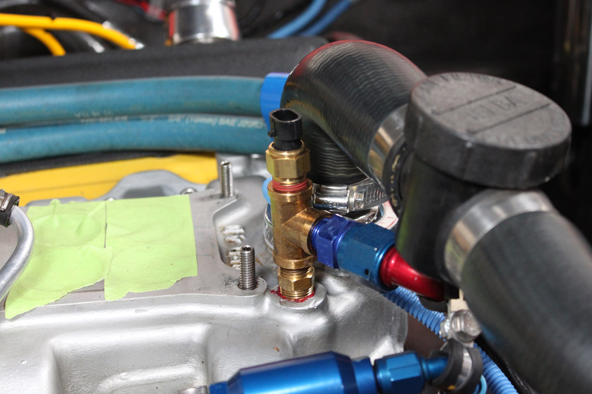
To use the port from your heater hose, a simple brass tee-fitting can be used like those in the illustration above. This allows for the hose connection still, as well as an additional port for the new sender. These brass fittings can be found at many auto parts stores like NAPA, or at home improvement stores. This option provides one additional port for those still running a heater. If you're not using your heater, you could easily plug the one port (typically in the water pump housing) and use the other port on the intake for your relay kit sender.
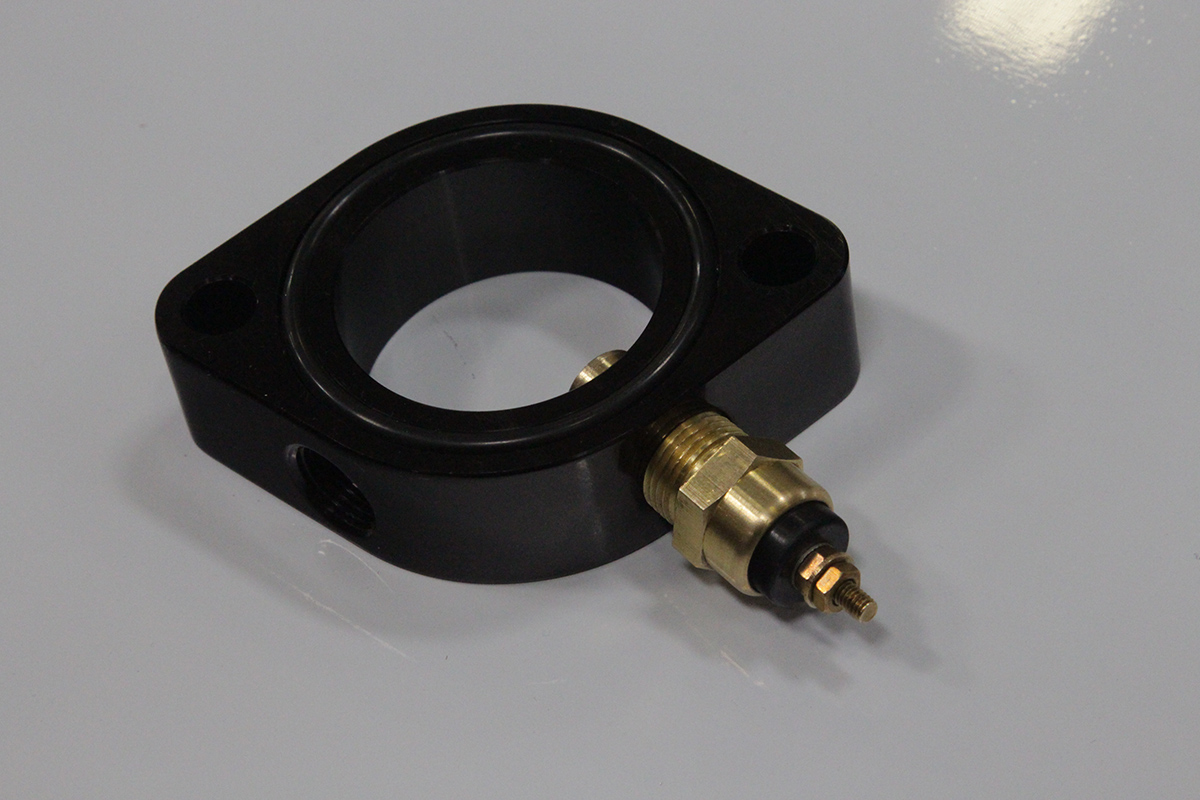
Another option, which is available at Summit and Jegs, is to purchase a thermostat housing spacer. This half-inch spacer fits between the intake manifold and thermostat housing, and provides two additional ports for additional senders and switches. If only one is needed, the second one can be plugged. It's best to make sure where you have the most room/access for the sender before you seal everything up, so do some test fitting and make sure that you can install the sender after the spacer is in place. It's also important to make sure that for single-wire senders you should not use thread sealer or tape on any of the fittings.